Hydro-Gear Pump purchase price + excellent sale
How does a hydro gear pump work? A mechanical device known as a hydraulic pump transforms mechanical energy into hydraulic energy
It generates flow with enough force to counteract the load’s pressure
When activated, the hydraulic pump serves two purposes
The fluid is forced out of the tank by air pressure after which it is pumped through the pump inlet line thanks to the mechanical action of the pump, which first creates a vacuum at the pump inlet
Second, the fluid is moved by the pump’s mechanical action and pushed into the hydraulic system
Which hydraulic pumps come in the most popular varieties? Rotary pumps, gear pumps, and radial piston pumps are the three most popular types of hydraulic pumps
All are suitable for typical hydraulic applications, but piston designs for higher pressures are advised
Positive displacement pumps make up the majority of pumps used in hydraulic systems
This indicates that the same volume of fluid is displaced (delivered) throughout each revolution of the pumping element
Regardless of pressure variations, the supply volume every cycle remains roughly constant
Pumps with positive displacement can have fixed or variable displacement assemblies
A fixed displacement pump’s output stays consistent at a specific pump speed throughout each pumping cycle
The output of the variable volume pump is altered by altering the shape of the volume chamber Dosing pumps, also known as screw pumps, are perfect for usage in theatres and opera houses because of how quiet they are
Variable displacement pumps, on the other hand, are very helpful in circuits that use hydraulic actuators and need the ability for variable speed or return
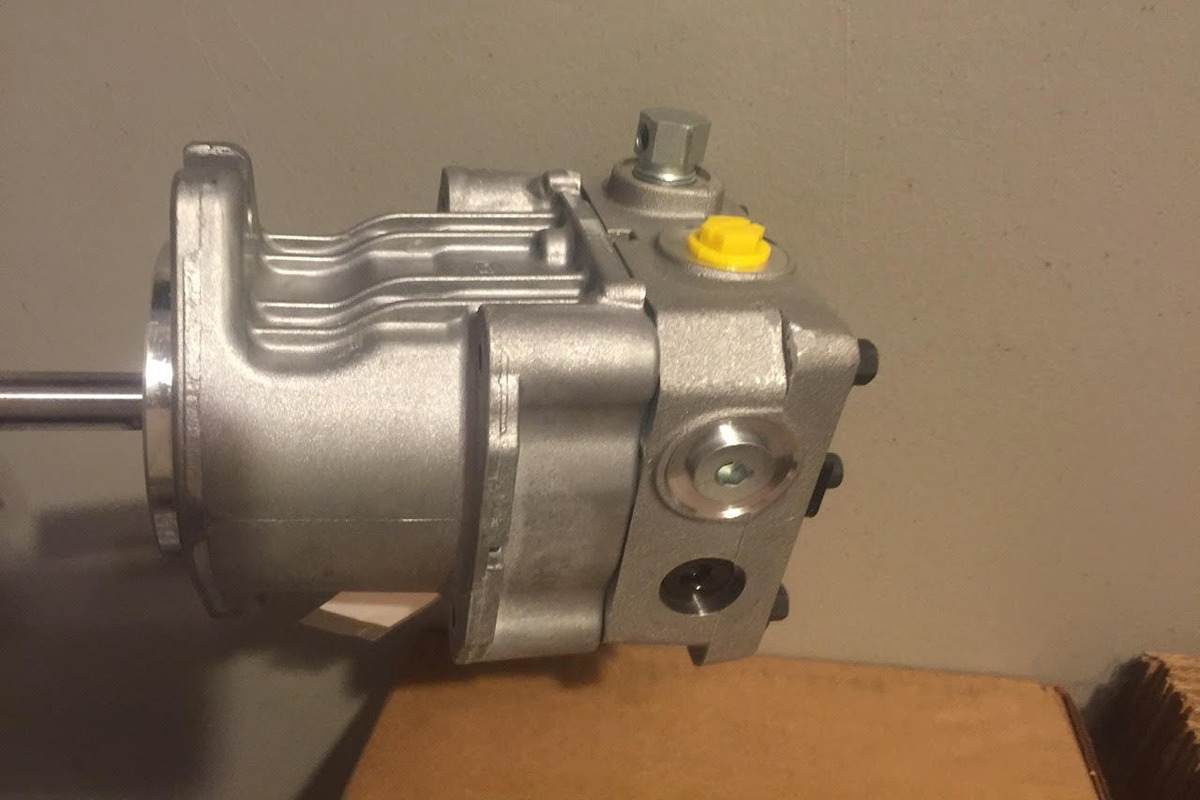
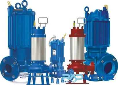
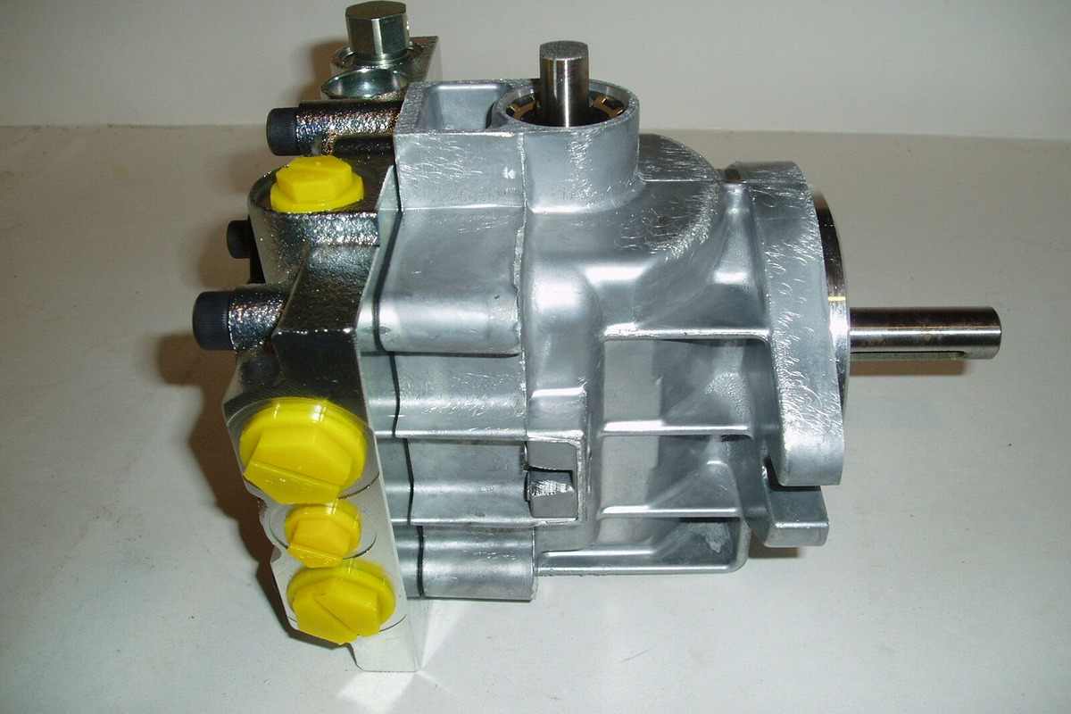
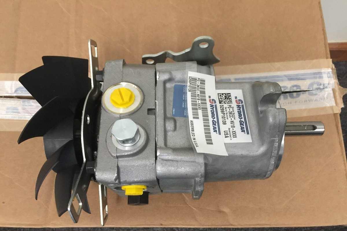
Hydro Gear Pump
A positive displacement (PD) pump is what the hydro gear pump is
It moves fluid mechanically utilizing a cyclic pumping action and repeatedly enclosing a fixed volume with gears or interlocking gears
In relation to the gear speed, it produces a smooth, pulsating flow
How is a gear pump operated? Gear pumps transport fluids by using the motion of rotating gears
At the pump inlet, the revolving element induces suction by creating a liquid seal with the pump casing
The pump’s spinning gear chamber holds the liquid that is drawn into it and directs it to the discharge port
There are two fundamental types of gear pumps: exterior and internal
Auxiliary gear pumpTwo interlocking gears supported by independent shafts make up external gear pumps
Typically, a motor powers one gear, which powers another gear (idler)
Both axes may occasionally be powered by electric motors
Bearings on either side of the framework support the shaft
The volume expands as a result of the gears separating from the pump’s input side
Fluid pours into the bore and is caught by the gear teeth as the gear continues to revolve in opposition to the pump housing
From the entry to the drain, the trapped fluid round the housing
The volume is reduced and the fluid is squeezed under pressure when the gear teeth on the pump’s discharge side mesh
There is no fluid transmission back through the centre between the gears since they are linked
The pump can provide suction at the intake and prevent fluid leakage from the discharge side thanks to the severe tolerances between the gears and casing (although low viscosity fluids are more prone to leakage)
Designs for external gear pumps may employ spur, helical, or spur gears
Inside-gear pumpThe two interlocking gears in internal gear pumps operate on the same principle, but because of differences in size, one gear spins inside the other
The largest gear (rotor), which has teeth that protrude from the inside, is an internal gear
It has an eccentrically positioned smaller external gear (the idler), which only drives the rotor
The gear teeth will mesh at one point because to how this is made to mesh with the rotor
The idler is held in place by a tiny gear and bushing that are fastened to the pump housing
The void left by the hysteresis unit’s off-center installation location is filled with a fixed spacer or semilunar spacer, which also serves as a seal between the inlet and exit ports
The volume expands as a result of the gears separating from the pump’s input side
Fluid pours into the bore and is caught by the gear teeth as the gear continues to revolve in opposition to the pump housing and diaphragm
From the entry to the drain, the trapped fluid round the housing
The volume is reduced and the fluid is squeezed under pressure when the gear teeth on the pump’s discharge side mesh
Designs for internal gear pumps exclusively employ spur gears
What are the key characteristics and benefits of gear pumps? Gear pumps are small, straightforward devices with few moving parts
They cannot equal the flow or pressure of a centrifugal pump, but they can provide more pressure and output than a vane or lobe pump
Oil and other high viscosity fluids are particularly well suited for gear pumps
Due to stiffer shaft supports and tighter tolerances, external gear pumps are better suited to manage higher pressures (up to 3000 psi) and flow rates than internal gear pumps
High viscosity fluids can be sucked up more effectively by internal gear pumps, albeit they only have a useful operating range of 1cP to over 1,000,000cP
Gear pumps are frequently employed for metering and mixing operations since their output is related to rotational speed
Corrosive fluids can be handled with gear pumps
New alloys and compounds enable the pump to handle corrosive liquids including sulfuric acid, sodium hypochlorite, ferric chloride, and sodium hydroxide, despite the fact that they are normally built of cast iron or stainless steel
Additionally, external gear pumps are utilized in hydraulic power applications, which are frequently found in vehicles, hoisting equipment, and mobile plant machinery
uses oil pushed from another part of the system (often via a tandem pump in the engine) to operate the gear pump in reverse, creating a hydraulic drive
This is especially helpful for energy conservation while using bulky, pricey, or otherwise inconvenient electrical equipment
For instance, external gear pumps powered by a motor are used to power services in tractors
What are a gear pump’s limitations? Although they can be dry-lifted and are self-priming, gear pumps perform better when the gears are wet
The fluid being pushed needs to lubricate the gears, and they shouldn’t be allowed to dry out for too long
For instance, certain gear pump designs allow for 360-degree rotation, allowing the pump to be used for both container loading and unloading
These sorts of pumps are prone to wear because of the close tolerances between the gears and housing, especially when used with abrasive fluids or feeds that contain entrapped materials
However, some gear pump models, particularly internal variations, may handle solids
Four bearings in the pumped medium are present in external gear pumps, but these bearings are tighter and less suited to handle abrasive fluids
Due to the fact that only one bearing (occasionally two) is immersed in the fluid, internal gear pumps are more potent
To shield them from big, potentially dangerous solids, gear pumps should always have a filter on the suction side
In general, it is advised to select a pump with a bigger capacity so that it can run at a lower speed to prevent wear if the pump is expected to handle abrasive solids
However, it is important to keep in mind that a gear pump’s volumetric efficiency declines at low speeds and flow rates
The gear pump’s operating speed shouldn’t deviate much from the suggested speed
It is crucial to confirm that the operating temperature range for high temperature applications is compliant with the pump’s specifications
Reduced clearances within the pump can result from thermal expansion of the casing and gears, which can cause increase wear and, in severe circumstances, result in pump failure
Even with the finest care, gear pumps frequently experience long-term gear, housing, and bearing wear
The pumped fluid leaks from the vacuum side to the suction side as the clearance increases, which also causes a steady drop in efficiency and an increase in flow slip
Wear generally has little impact until a critical point is reached where performance rapidly degrades because flow slip is proportional to the cube of the gap between the sprocket and the housing
When faced with a blockage downstream, gear pumps continue to pressurize the system against back pressure until the pump, piping, or other equipment fails
Despite the fact that the majority of gear pumps have relief valves installed for this purpose, it is always advised to install relief valves in other parts of the system to safeguard end equipment
Internal gear pumps are typically used for shear-sensitive liquids like food, paint, and soap since they run at low speeds
These applications are inappropriate for the external gear design due to its high speed and small surface area
Due to its mechanical simplicity and convenience of disassembly, cleaning, and reassembly, internal gear pumps are also favored when cleanliness is a concern
How Does a Gear Pump Work
One type of metering pump is the gear pump
How does it work? Positive displacement pumps can be divided into metering pumps and other similar types
Each vacuum or pump cycle has a predetermined volume
Back pressure has little effect on emissions
The precision of metering pumps and positive displacement pumps differs from one another
The metering pump’s average accuracy is 1
0%
Metering pumps come in a variety of classes, such as peristaltic, piston, gear, and diaphragm pumps, all of which feature constant-volume chambers that provide the same volume throughout each pumping cycle
Controlling bore volume and lowering leakage and dead volume is thus the key to every metering pump design
The subject of this blog is gear pumps
How gear pumps operate By trapping fluid between the teeth of two or three revolving gears, gear pumps function
Since they are frequently magnetically activated, they require less “wetting” substances and have higher chemical compatibility
Instead of driving a reciprocating cavity, gear pumps drive a rotating cavity
These pumps don’t pulse as frequently as diaphragm pumps since they move multiple tiny cavities per cycle
The main drawback of gear pumps is that they have a lower flow when the back pressure is increased
It functions best when continuously under back pressure
Gear pumps are better suited for applications where fluid shear or particle contamination due to gear wear are not a problem since they transfer fluid between the teeth of two or three rotating gears during operation
These pumps work well in high system pressure applications and are frequently used in high viscosity fluids like non-compressible lubricants as well as hydraulic fluid power applications like tractors and garbage trucks
The gear pump offers a precise volume per revolution due to its genuine positive displacement
The flow rate is essentially pulse-free due to the small size of each fluid pocket and the high number of pockets that move through the chamber in a given amount of time
Gear pumps effectively give quick reaction, continuous flow, and accurate metering thanks to their metering, circulation, metering, and transfer characteristics
Gear pumps are used by analytical chemists for flash chromatography, fluid handling, melt testing, and sample dilution
These pumps handle liquids for a range of industrial applications, including applying optical bleach to paper, gauging tastes and scents, and pouring sprayed wax coatings to meals
They can be found in the manufacturing of paint and ink, labs, pharmaceuticals, and industrial facilities as well as in the processing of chemicals
Peripheral gear pumps Even though peristaltic pumps have many benefits, gear pumps can occasionally be preferable
In comparison to peristaltic pumps and just slightly broader than hose pumps, gear pumps have a larger flow capacity
There is little to no fluid absorption because the gear pump enables stronger tubing as the solution enters and exits the pump
On the other hand, peristaltic pumps work with looser tubes that permit some fluid absorption and fluctuation
Because the user must turn on the pump to clean the gears and pump head, gear pumps take more maintenance time than peristaltic pumps
Additionally, the chemical compatibility of gear pumps may be restricted, and the material used in gear pumps is frequently stainless steel, PTFE, or PEEK
Finally, the gear pump struggles to accept the filthy particles inside of it
A peristaltic pump might be the best option in this situation
When a clean, consistent flow of granular fluids is required, gear pumps are frequently the best option
Gear pumps are the suggested option, for instance, in industrial applications like pumping inks and coatings or pipe injection
Shoe suction design versus cutout designA motor plus a pump head make up a gear pump
The following two alternative gear pump heads are combined with the most popular drives
High inlet pressures can be handled by the hole pattern
The tight seal between the gear teeth is maintained by ambient fluid pressure in a magnetic cup and two or more rotating gears that mesh together
Applications requiring a suction stroke, frequent rotation, or pressure intake are best suited for this pump head
Higher delivery pressure and better preparation performance are provided by suction cup design
The entrance of pressure loaded pump heads is encircled by a suction shoe
The gear and suction shoe are held firmly together by the high pressure in the magnetic cup against the inlet side
By guaranteeing complete fluid transfer without backflow or leakage between gear tips, even at high pressures, this design enhances volumetric accuracy
These pump heads function effectively in situations that need high starting differential pressure and precise flow because pump efficiency rises with discharge pressure