Water Vane Pump Hydraulic | buy at a cheap price
Hydraulic systems frequently make use of the balanced vane pump as a component of the water transmission
Because of the differences in the physical and chemical properties of water and seawater compared to those of mineral oils, several issues might develop, including inadequate lubrication, increased filtration, and increased wear
These issues can be avoided by using mineral oils
The purpose of this document is to provide light on the question of whether or not a hydraulic vane pump is technically feasible
The material groupings were decided upon after searching for relevant information in the relevant literature
In this experiment, both the volumetric efficiency and the suction performance were examined
Mathematical models were used to simulate the relationships between air gaps, leakage rate, contact and friction forces between the blade tip and the cam circumference
This was done in order to better understand these linkages
When tested, typical combinations of hard and soft pump materials display favorable frictional qualities
Endplay is the primary pathway for the flow of leaks
The pin vane pump can lower the vane tip contact force
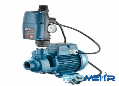
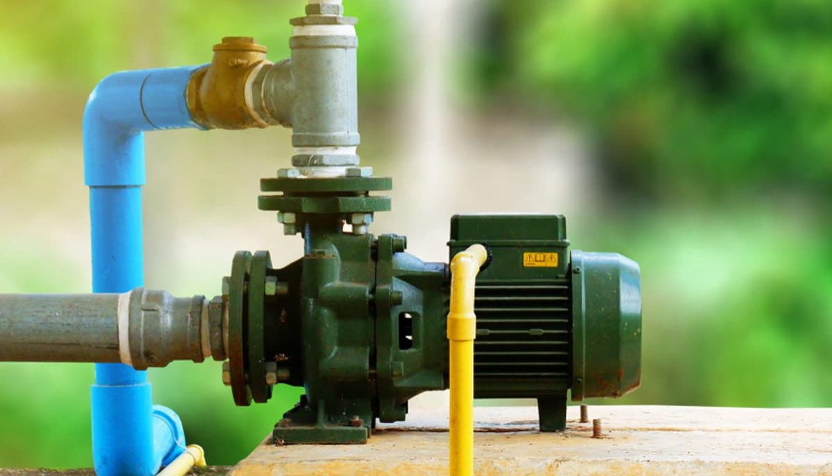
The vane pump is a self-priming positive displacement pump that provides constant flow at varying pressures
It is driven by a motor connected to a gearbox
The maximum RPM is usually 900
The pump is equipped with a pressure relief valve to prevent the pump from overpressure that could damage it
The pump head has a separate rotor that contains rotors
The rotors create segmented chambers within the pump head, dividing the pump head between the rotor and the outer casing, allowing the vane pump to be self-priming because the chambers act as valves
The pump head is mostly circular, but has a flat area where the blades enter and leave the main rotor
The vanes will push into the casing due to the centrifugal force when the pump is running, and external forces will keep the vanes tight against the casing
When the rotors reach the pump outlet, the casing is flat and tighter against the rotor, causing the vane to push toward the rotor and the fluid out of the pump outlet
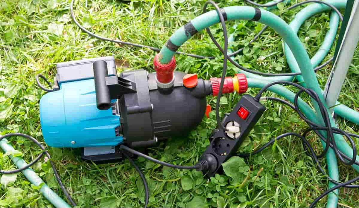
Vane pumps are reversible, making them an excellent choice for tank draining and emptying
It can then be run in reverse to fill tanks or load vehicles as the pump can run in either direction
As a rule, vane pumps are equipped with a single mechanical seal or a double mechanical seal with a diaphragm fluid or a stuffing box
Typically used to lubricate viscous fluids such as petroleum, petroleum, diesel, animal/blood oils and fuel oil
They can also handle non-lubricated liquids, such as solvents, because there is no metal-to-metal contact
Vane pumps automatically compensate for wear, which means they can maintain peak performance without loss of flow
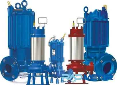
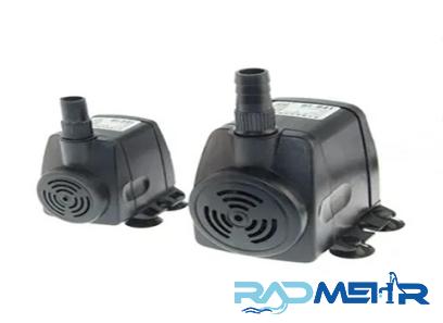
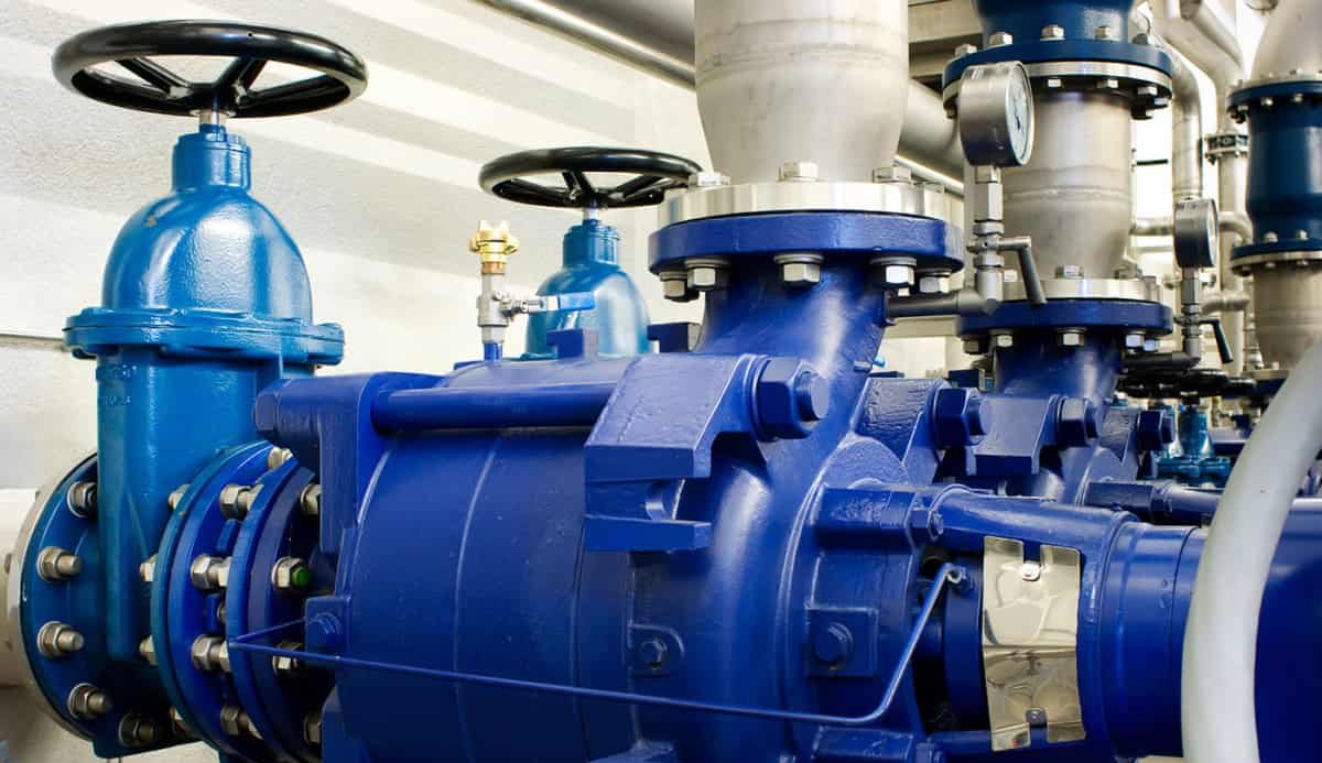
Water Vane Pump
There is a variety of rotary positive displacement water pumps known as vane pumps
A set of blades in the shape of paddles that are mounted radially on a cylindrical rotor produce a series of compartments that are capable of holding fluids and transferring them from one location to another throughout the system
Because the rotors always keep a snug fit against the wall of the pumping chamber, there is no chance of liquid flowing back through the pump
When it comes to pumping thin fluids at high pressure, vane pumps are among the most effective options
These pumps have a low pulsation output, accurate flow rates, and contain solid components that are resistant to wear and will lengthen the life of the pump
As a result of the position of the eccentric mounting of the rotor, there is a change in volume that occurs between adjacent blades as the rotation cycle progresses
This results in a pumping action being created
Sliding vane pumps and flexible vane pumps are the two primary varieties of vane pumps that are available
In a sliding rotary pump, the vanes are put into radial holes in a cylindrical rotor
The blades rest in their slots when the pump is turned off
But when the shaft turns fast enough (about 700 times per minute), the blades move outward because of centrifugal force and stay close to the cam ring that is drilled into the wall of the crankcase
The rotors can also be made with springs that keep them in contact when the pump is turned off
Any wear on the edges of the blades is made up for by making the blades longer
In a flexible vane pump, the rotor, or impeller, is made of an elastic material and has several elastic lobes that stay in contact with the perforated cam ring and the pump body
The rotor is upside down and slightly bigger than the pump body
This means that the rotors shrink on the “short” side of the cycle and then grow again on the “long” side as they conform to the shape of the pumping chamber
This creates chambers between the blades that expand at the pump’s inlet to create suction and contract at the pump’s outlet to create a vacuum
Since the rotor lobes are bigger than the pump body, they can take some wear
The casings of vane pumps can be balanced, not balanced, or variable
The pumps are not balanced because the rotor is off-center: the center of the shaft is not in the same place as the center of the pump body
Different pressures at the inlet and outlet can cause the shaft bearings to shake and wear out faster
In a balanced design, the center of the pump casing and the center of the rotor are the same
To do this while still doing the same job, the pump bore is not round but rather elliptical
Since the pump’s inlets and outlets are on opposite sides, there is no difference in pressure
The size of the pumping chamber can be changed in the variable design
With this function, you can change how fast the pump delivers water
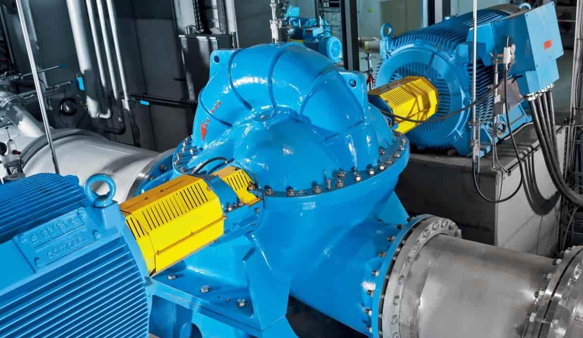
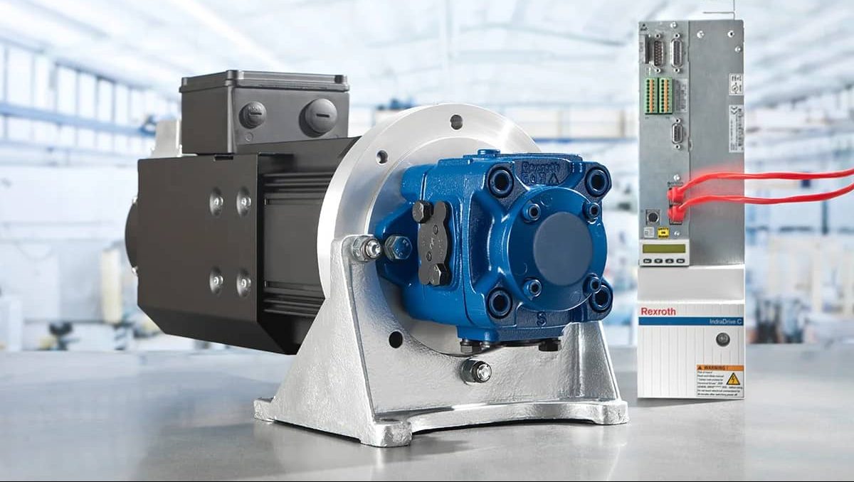
Vane Hydraulic Pump
Vane pumps are a sort of hydraulic pump that may function with a very low amount of background noise
The flow through hydraulic vane pumps is relatively consistent, as the pumps work with substantially reduced flow pulsations
Therefore, vane pumps generate less noise despite operating at a relatively high speed of 3,000 revolutions per minute
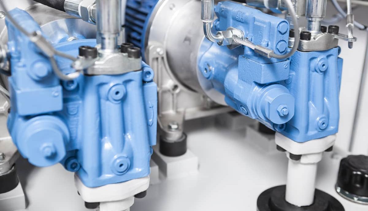
Small hydraulic vane pumps having a displacement size of more than 50 cc, such as the Parker Denison T7A or T7B, have a maximum speed of 3600 rpm at hydraulic system pressures of 300 bar intermittently
This is due to the fact that the displacement capacity of these pumps is greater than 50 cc
This is the compartment despite the fact that the forces of the market are always shifting
In the manufacturing sector, hydraulic vane pumps find use in machinery that is used for injection molding, as well as for the construction of roads and other land
Vane pumps have an operating pressure range that normally falls between 180 and 210 bar
However, the working pressure can be greater than 200 bar and can even be as high as 300 bar in vane pumps that are specially designed
Parker Hannifin utilizes Denison vane technology in the production of the industry’s finest fixed displacement balanced vane pumps, which are sold by the company under the brand name Denison
Different hydraulic systems and functional needs, such as the working medium, required pressure range, motor type, and so on, are taken into consideration throughout the manufacturing process of hydraulic pumps
Our sales engineers will assist you in selecting the hydraulic pump that is most suitable for your particular application
Whenever the machine is in motion, the blades are pressed up against the cam ring by the application of pressure from the hydraulic system within
Because of the hole on one side of the rotor hole, pressurized oil is able to enter the cavity that is located between the vane and the vane insert
This causes the insert to function as a miniature piston
When the insert is pressed against the bottom of the rotor hole, the oil pressure that is located between the top of the insert and the vane provides a controlled and uniform force that keeps the vane from falling into the hole
Any oil that is present in the groove underneath the vane on both sides of the inlet has the potential to flow through the drilled holes and into the rotor’s outer diameter
The vanes move in a manner that is consistent with the cam ring’s inner circumference as the rotor is rotated by the shaft
Between the rotor and the cam ring, there are two points where the clearance is at its minimum, and there are also two points where the clearance is at its maximum